
经过上一节我们通过Gazebo的界面创建了机器人保存之后,在~/model_editor_models中会有一个my_robot_gui的文件夹,里面有两个文件,一个是model.sdf是用于描述机器人的SDF文件,可以打开看到是一个XML文件。另外一个是model.config是用于描述此model的元数据
SDF模型介绍
SDF文档的写法在官网写的比较详尽,对于任何一个元素都有相应的结构和写法
譬如一个world文件:
1 |
|
在整个world中,我们加载了非机器人的模型文件以及两个机器人,注意,在model文件里也可以嵌套加载一个model,可以查看官网。
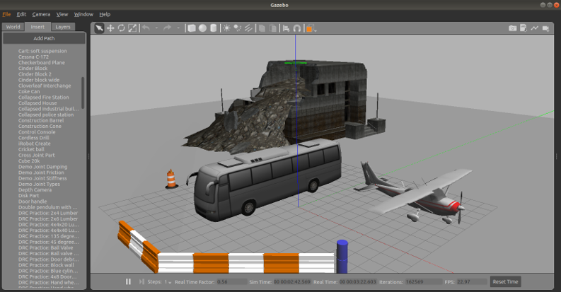
在gazebo中, 也有很多已经存在的模型供我们使用。找到左侧的insert栏目,点击相应的名称即可插入模型。常用的模型有室内环境、楼房、各种材质地形、围墙等,甚至还有整个城市的粗模型,用于搭建机器人的工作环境;一些水瓶、桌椅等小物品可以与机器人交互。
下面我们介绍如何通过SDF文件来创建一个和model 编辑器一样的机器人来学习一下基本标签内容
模型建立
首先是建立一个文件夹
1
2mkdir ~/model_editor_models/my_robot_sdf
cd ~/model_editor_models/my_robot_sdf一样的,我们建立两个文件
1
2touch model.config
touch model.sdf首先是对model的内容进行配置
1
2
3
4
5
6
7
8
9
10
11
<model>
<name>my_robot_sdf</name>
<version>1.0</version>
<sdf version="1.7">model.sdf</sdf>
<author>
<name>your name</name>
<email>your email</email>
</author>
<description>Some description here</description>
</model>打开model.sdf,添加xml文件标签,以及SDF标签:
1
2
3
4
5<sdf version='1.7'>
<model name="my_robot_sdf">
...
</model>
</sdf>在model标签中的内容就是我们在GUI中所涉及的元素内容的编写,例如link,visual,collision等等。下面我们先编写底盘部分
在gazebo中任何物体就是一个link,比如机器人的底盘,任何一个驱动轮,万向轮等等。每一个link都至少需要三个属性
- visual:视觉外观看起来的属性
- collision:内容和visual一样,但是表示的是实际判定碰撞时候用到的大小
- inertial:惯性,物理引擎使用惯性信息来计算模型在受力时的行为
我们首先给出visual,将下面的代码直接粘贴到
<model>标签里面1
2
3
4
5
6
7
8
9
10
11
12
13
14
15
16
17
18
19
20
21
22
23
24
25
26
27
28
29
30
31
32<link name="base_link">
<!-- 这里表示xyz rpy -->
<pose>0 0 0.09 0 0 0</pose>
<visual name="base_visual">
<geometry>
<cylinder>
<radius>0.20</radius>
<length>0.16</length>
</cylinder>
</geometry>
</visual>
<collision name="base_collision">
<geometry>
<cylinder>
<radius>0.20</radius>
<length>0.16</length>
</cylinder>
</geometry>
</collision>
<inertial>
<mass>20</mass>
<inertia>
<ixx>0.24</ixx>
<ixy>0</ixy>
<ixz>0</ixz>
<iyy>0.24</iyy>
<iyz>0</iyz>
<izz>0.4</izz>
</inertia>
</inertial>
</link>其中,
pose代表的属性为$x, y, z,r, p, y$, 代表整个link中心点的位置和旋转,我们通过visual标签使base_link的外形看起来是一个圆柱体,其中半径为0.20,高度为0.16,并设置相同的实际碰撞的大小。保存退出,此时我们再一次打开Gazebo,在仿真模式下左侧栏选择
Insert选项卡,在model_editor_models文件夹下会有我们上面所创建的机器人my_robot_sdf, 鼠标单击将其拉到场景中,可以看到
接下来我们添加左轮,和添加底盘的操作是一样的,也包括三部分,visual,collision和inertial
1
2
3
4
5
6
7
8
9
10
11
12
13
14
15
16
17
18
19
20
21
22
23
24
25
26
27
28
29
30
31<link name="left_wheel_link">
<pose>0 0.19 0.06 1.5707 0 0</pose>
<visual name="left_wheel_visual">
<geometry>
<cylinder>
<radius>0.06</radius>
<length>0.025</length>
</cylinder>
</geometry>
</visual>
<collision name="left_wheel_collision">
<geometry>
<cylinder>
<radius>0.06</radius>
<length>0.025</length>
</cylinder>
</geometry>
</collision>
<inertial>
<mass>2</mass>
<inertia>
<ixx>0.0019</ixx>
<ixy>0</ixy>
<ixz>0</ixz>
<iyy>0.0019</iyy>
<iyz>0</iyz>
<izz>0.0036</izz>
</inertia>
</inertial>
</link>我们设置高度为0.06,和半径一样,使得左轮刚好停在地表面上。注意现在只是一个单独的link. 我们还需要为
"left_wheel_link"和base_link添加一个joint。在这joint的中,我们需要定义parent、child以及旋转轴。注:joint和其他的link是同级的。类型type和我们使用Gazebo时创建左轮的类型一致1
2
3
4
5
6
7<joint name="left_wheel_joint" type="continuous">
<parent>base_link</parent>
<child>left_wheel_link</child>
<axis>
<xyz>0 0 1</xyz>
</axis>
</joint>再一次从Gazebo里面将
my_model_sdf拽入场景中,右键点击物体,选择view->transparent可以使物体透明
接下我们添加右轮,也为其添加和base_link的joint
1
2
3
4
5
6
7
8
9
10
11
12
13
14
15
16
17
18
19
20
21
22
23
24
25
26
27
28
29
30
31
32
33
34
35
36
37
38<link name="right_wheel_link">
<pose>0 -0.19 0.06 1.5707 0 0</pose>
<visual name="right_wheel_visual">
<geometry>
<cylinder>
<radius>0.06</radius>
<length>0.025</length>
</cylinder>
</geometry>
</visual>
<collision name="right_wheel_collision">
<geometry>
<cylinder>
<radius>0.06</radius>
<length>0.025</length>
</cylinder>
</geometry>
</collision>
<inertial>
<mass>2</mass>
<inertia>
<ixx>0.0019</ixx>
<ixy>0</ixy>
<ixz>0</ixz>
<iyy>0.0019</iyy>
<iyz>0</iyz>
<izz>0.0036</izz>
</inertia>
</inertial>
</link>
<joint name="right_wheel_joint" type="continuous">
<parent>base_link</parent>
<child>right_wheel_link</child>
<axis>
<xyz>0 0 1</xyz>
</axis>
</joint>注意这里

添加万向轮前轮,注意link的类型为ball
1
2
3
4
5
6
7
8
9
10
11
12
13
14
15
16
17
18
19
20
21
22
23
24
25
26
27
28
29
30
31
32
33<link name="caster_front_link">
<pose>0.18 0 0.015 0 0 0</pose>
<visual name="caster_front_visual">
<geometry>
<sphere>
<radius>0.015</radius>
</sphere>
</geometry>
</visual>
<collision name="caster_front_collision">
<geometry>
<sphere>
<radius>0.015</radius>
</sphere>
</geometry>
</collision>
<inertial>
<mass>0.5</mass>
<inertia>
<ixx>0.000045</ixx>
<ixy>0</ixy>
<ixz>0</ixz>
<iyy>0.000045</iyy>
<iyz>0</iyz>
<izz>0.000045</izz>
</inertia>
</inertial>
</link>
<joint name="caster_front_joint" type="ball">
<parent>base_link</parent>
<child>caster_front_link</child>
</joint>以及万向轮后轮
1
2
3
4
5
6
7
8
9
10
11
12
13
14
15
16
17
18
19
20
21
22
23
24
25
26
27
28
29
30
31
32
33<link name="caster_back_link">
<pose>-0.18 0 0.015 0 0 0</pose>
<visual name="caster_back_visual">
<geometry>
<sphere>
<radius>0.015</radius>
</sphere>
</geometry>
</visual>
<collision name="caster_back_collision">
<geometry>
<sphere>
<radius>0.015</radius>
</sphere>
</geometry>
</collision>
<inertial>
<mass>0.5</mass>
<inertia>
<ixx>0.000045</ixx>
<ixy>0</ixy>
<ixz>0</ixz>
<iyy>0.000045</iyy>
<iyz>0</iyz>
<izz>0.000045</izz>
</inertia>
</inertial>
</link>
<joint name="caster_back_joint" type="ball">
<parent>base_link</parent>
<child>caster_back_link</child>
</joint>这里也一样,设置了
pose中的z和半径一样大,是为了让球刚好在地表上。最后的机器人应该看起来长这个样子

加入sdf到world文件
除了在指定的目录下可以直接拖拽我们的sdf模型文件,还可以把他嵌入到一个世界文件中,例如新建一个名为my_robot_world.world
1 |
|
为了防止两个机器人初始位置重叠,我们添加语句
1 | <pose relative_to="robot1">1 0 0 0 0 0</pose> |
使得第二个机器人距离第一个机器人x轴上的位置为1.
添加环境变量
1 | export GAZEBO_MODEL_PATH=~/model_editor_models |
到相应的world所在的文件夹下
1 | gazebo my_robot_world.world -u |
就可以看到机器人加载到场景之中
